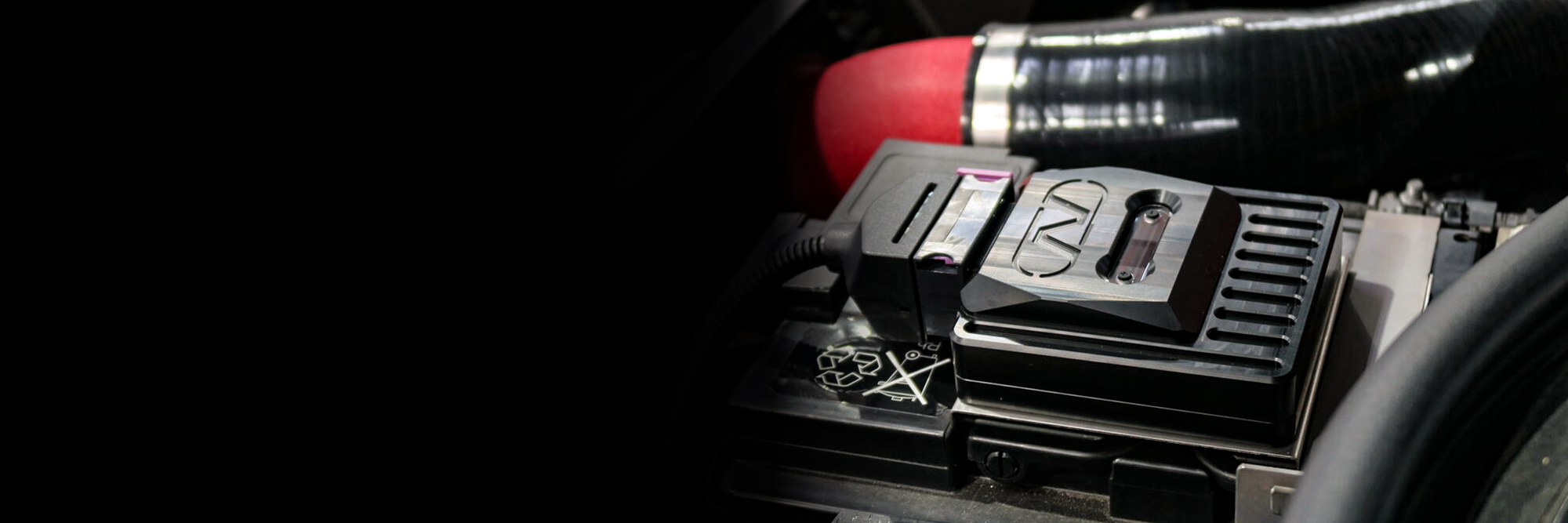


EXPERIENCE THE ALL-NEU POWER MODULE EVO
TOTAL TEUTONIC TUNING
For years, NEUSPEED® has been at the forefront of designing, engineering, and manufacturing not just parts, but comprehensive Automotive Performance Systems. While others may offer individual components, we specialize in creating harmonized solutions that extract the utmost performance from your vehicle.
Whether you upgrade incrementally or overhaul your car in one go, you can be confident of achieving peak performance consistently – just start the engine and feel the difference! So, when considering upgrades, why settle for standalone parts when you can invest in a fully integrated system of engineered performance?
BEST SELLERS


![NEUSPEED TDI Turbo Discharge Damper [sku] - NEUSPEED](http://neuspeed.com/cdn/shop/products/48.02.83.jpg?v=1750864978&width=800)

![Neu-F Torsion Bar - Rear 28mm [sku] - NEUSPEED](http://neuspeed.com/cdn/shop/products/NF.2528.jpg?v=1750864967&width=800)
![NEUSPEED Hi-Flo Turbo Inlet Pipe [sku] - NEUSPEED](http://neuspeed.com/cdn/shop/products/48.02.46.jpg?v=1750865026&width=800)

![NEUSPEED Anti-Sway Bar End Links - Rear [sku] - NEUSPEED](http://neuspeed.com/cdn/shop/products/32.10.91.jpg?v=1750864896&width=800)
![NEUSPEED Anti-Sway Bar - Rear 25mm [sku] - NEUSPEED](http://neuspeed.com/cdn/shop/products/25.02.25.5.jpg?v=1750865069&width=800)
![NEUSPEED Anti-Sway Bar Clamp & Bushing Kit w/ Grease Fitting [sku] - NEUSPEED](http://neuspeed.com/cdn/shop/products/HCB.25.02.28.3.jpg?v=1750864962&width=800)
![NEUSPEED TDI Turbo Discharge Damper [sku] - NEUSPEED](http://neuspeed.com/cdn/shop/products/48.02.84.jpg?v=1750864977&width=800)
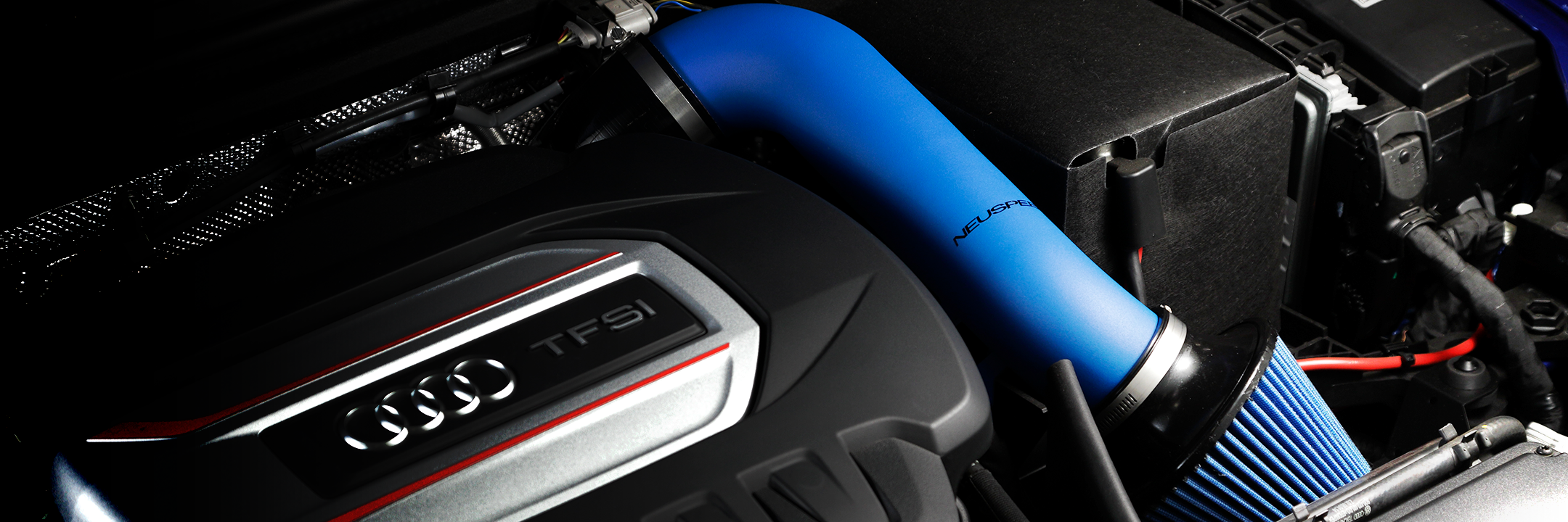
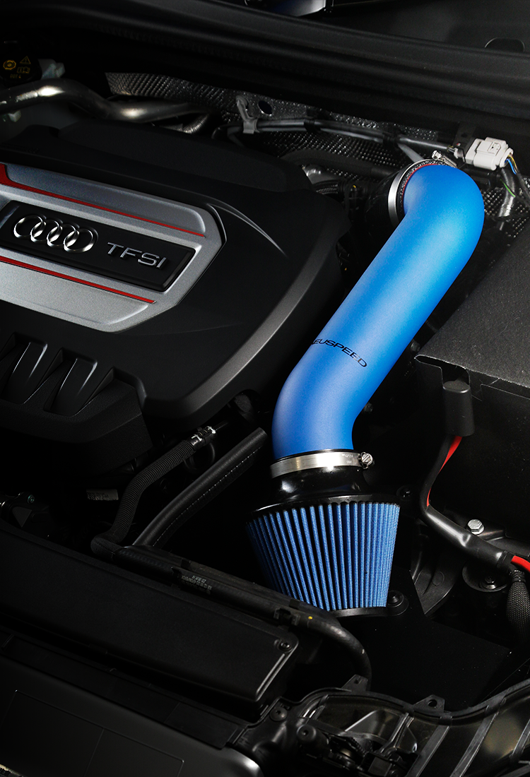
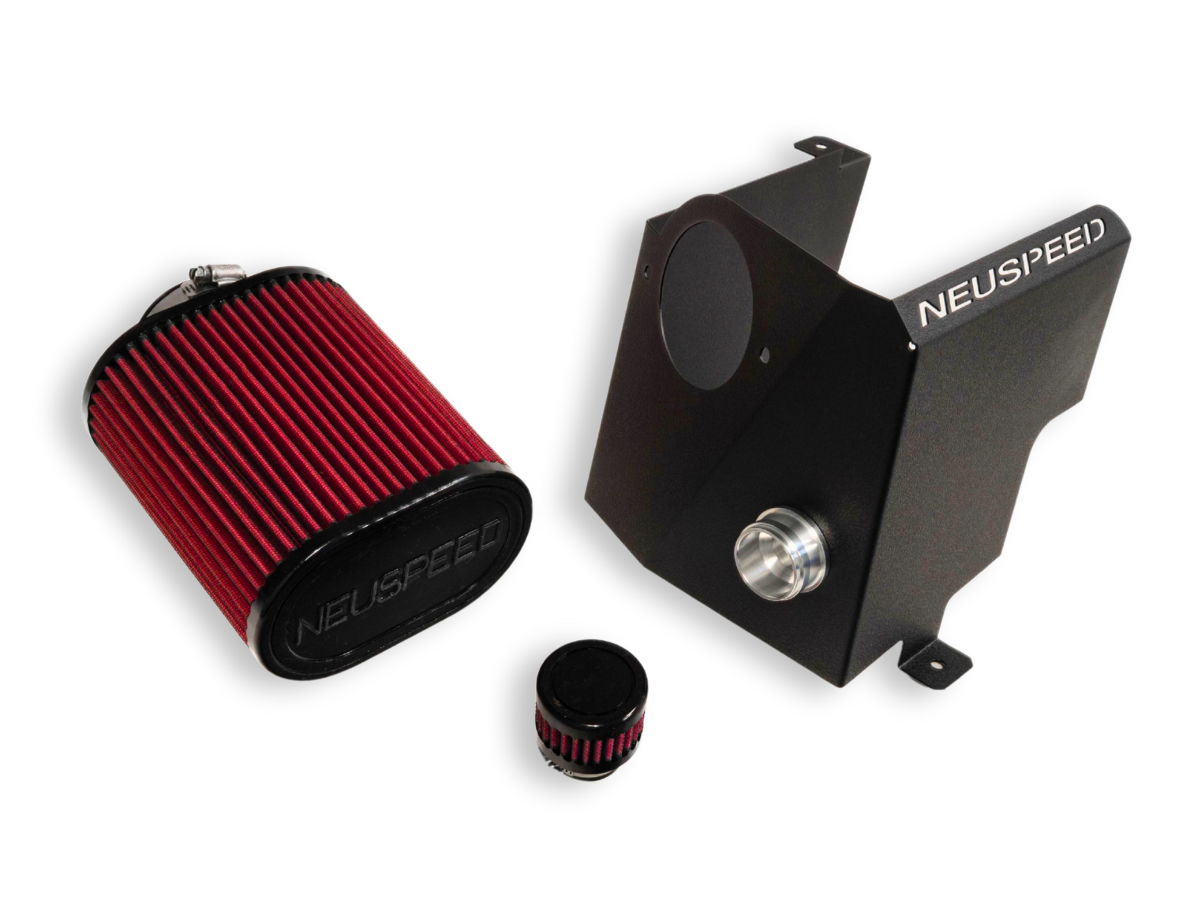
![Air Intake Kit | P-FLO • PQ35 2.0L EA888.1/2 TSI [sku] - NEUSPEED](http://neuspeed.com/cdn/shop/files/65.10.92-blkshield.jpg?v=1750864827&width=1000)
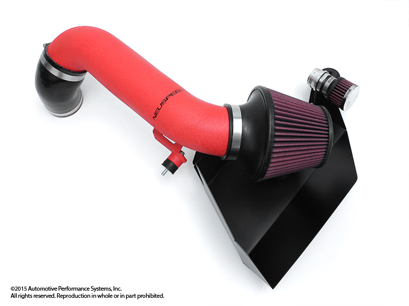
![Air Intake Kit | P-FLO • PQ35 2.0L EA888.1/2 TSI [sku] - NEUSPEED](http://neuspeed.com/cdn/shop/files/65.10.92R-blkshield.jpg?v=1750864827&width=1000)
![Air Intake Kit | P-FLO • PQ35 2.5L 5-Cyl [sku] - NEUSPEED](http://neuspeed.com/cdn/shop/products/65.10.99-80.jpg?v=1750865009&width=800)


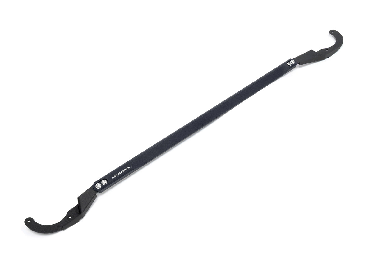
![Upper Strut Tie-Bar - Front • Golf/GTI/R Mk7/8 [sku] - NEUSPEED](http://neuspeed.com/cdn/shop/products/35.10.69-colors.jpg?v=1750864688&width=1600)
BROWSE BY CATEGORY
View all


BRANDS WE CARRY


3300 Corte Malpaso
Camarillo CA 93012
Monday - Friday: 8AM - 5PM PST
Saturday - Sunday : Closed
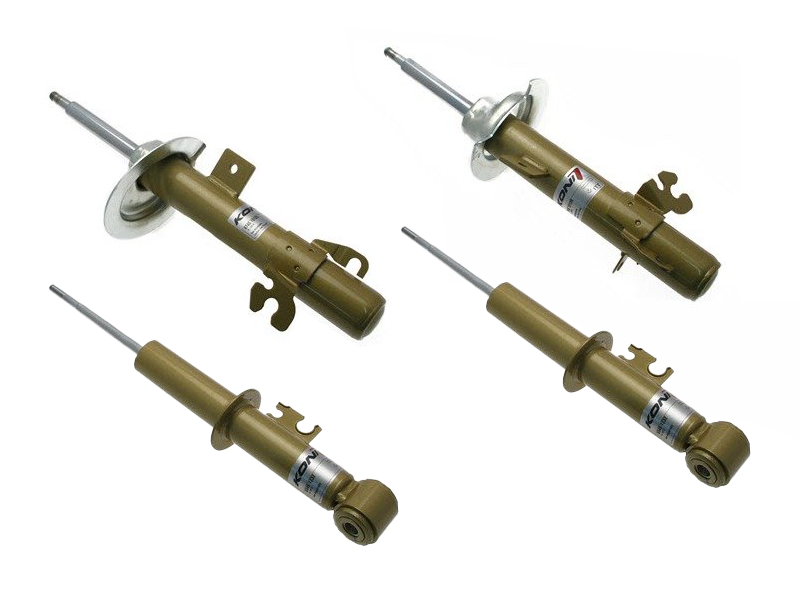
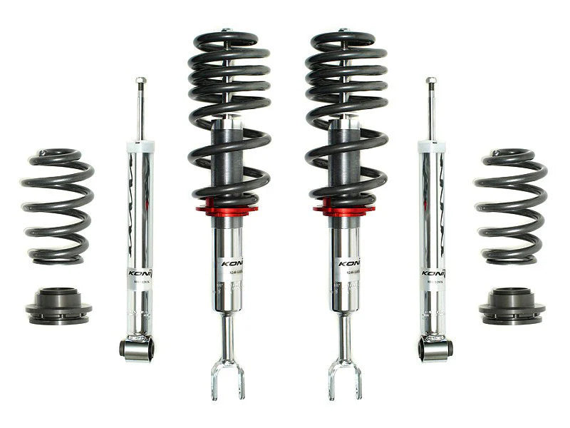
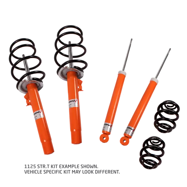
KONI CLEAN OUT SALE
Limited quantities. No restocks. Big savings.
We're clearing out our stash of KONI Shocks & Struts—brand new, in-box, and priced to move. These are leftover kits we've had on the shelves for years, so once they're gone, they're gone for good.